
Best Path
Get a view of the best connectivity routes for network optimization
Request a quote for Best path
Note: ultra-short routes are not part of the public network; you can check the actual information with the sales department. (Please send request to
Calculation is for reference only. Latencies / MTU are subject to check.
CONTACT
For any questions and enquiries, please feel free to contact our team at
If you experience a problem with this site, please report it to
Best Path is the name of our special tool used for illustrating correct latencies among backbone nodes of IPTP Networks.
WHY BEST PATH IS USEFUL?
Turning IPTP’s worldwide spread network map into detailed data, our own developed Best Path tool always gives a better visual display of routes and latencies. This is very useful for businesses aiming for network optimization.
Thanks to it, users can have a more understandable picture of each connectivity including protected paths, the availability of the paths, and other particular requirements. From this information, customers can freely design their optimal routes effortlessly.
To start the search:
1) Choose the desired nodes from the dropdown menu
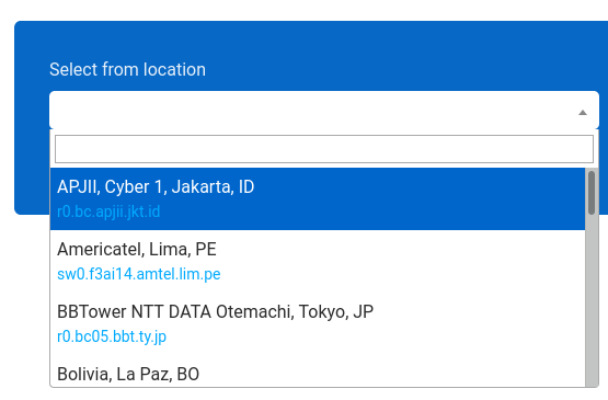
2) Choose suitable boxes. There are 4 supporting options to show you a more diverse result:
3) Click on the “Calculate Path” button to finish the search and see the results.
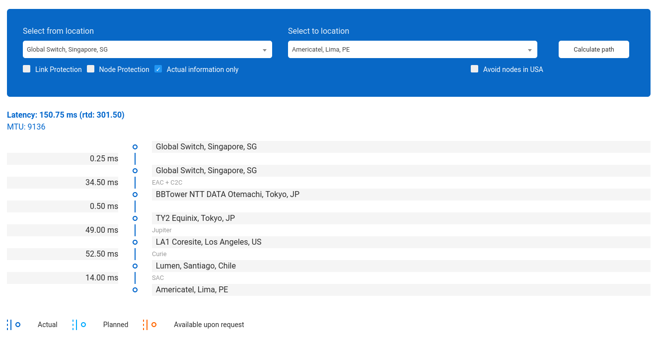
The result has 2 parts: the number and the map. This appears as the example below:
The number part shows all details about the requested route:
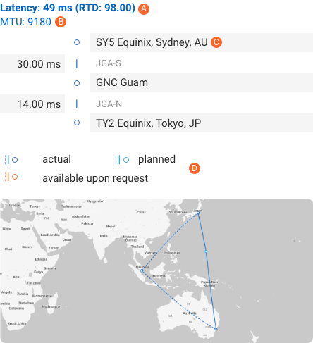
In which,
A) “Latency: 49 ms” is the latency of the whole route, with 98.00 ms is the RTD,
B) The maximum transfer unit (MTU) as usually around 9000,
C) “SY5 Equinix, Sydney, AU”, “GNC Guam”, and “TY2 Equinix, Tokyo, JP” are the nodes,
– “JGA-S” and “JGA-N” are the cables used in this path,
– “35.00 ms” and “14.00 ms” are the latencies,
– Dashed line: second route
– Dark blue line: actual route,
– Light blue line: a planned route for upcoming time,
– Orange line: routes are available only when requested.
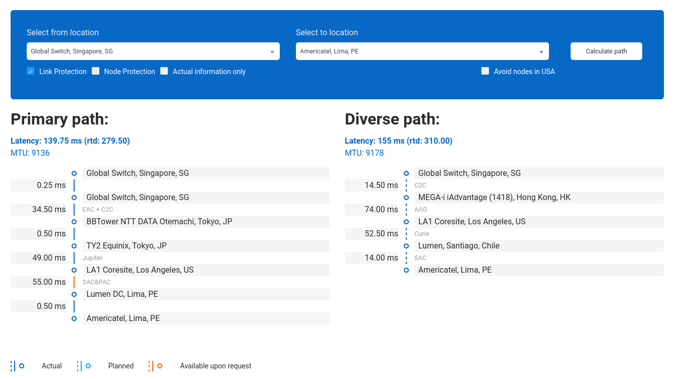
Normally, if you run the search without choosing any additional requirements, the result will show only the Primary path of the requested route. However, we also provide many options, as mentioned in step 2 of “How to use Best Path?”, to provide you with a more detailed answer including Diverse paths to be used as backup whenever the primary one is down.
Next, let’s take a closer look at the meaning of each supporting box of the Best Path tool for network performance optimization.
THE NUMBER PART
Link protection:
Together with the primary one, if you also wanna see Diverse paths (which avoid cables used in the Primary one), let’s choose “Link Protection”.
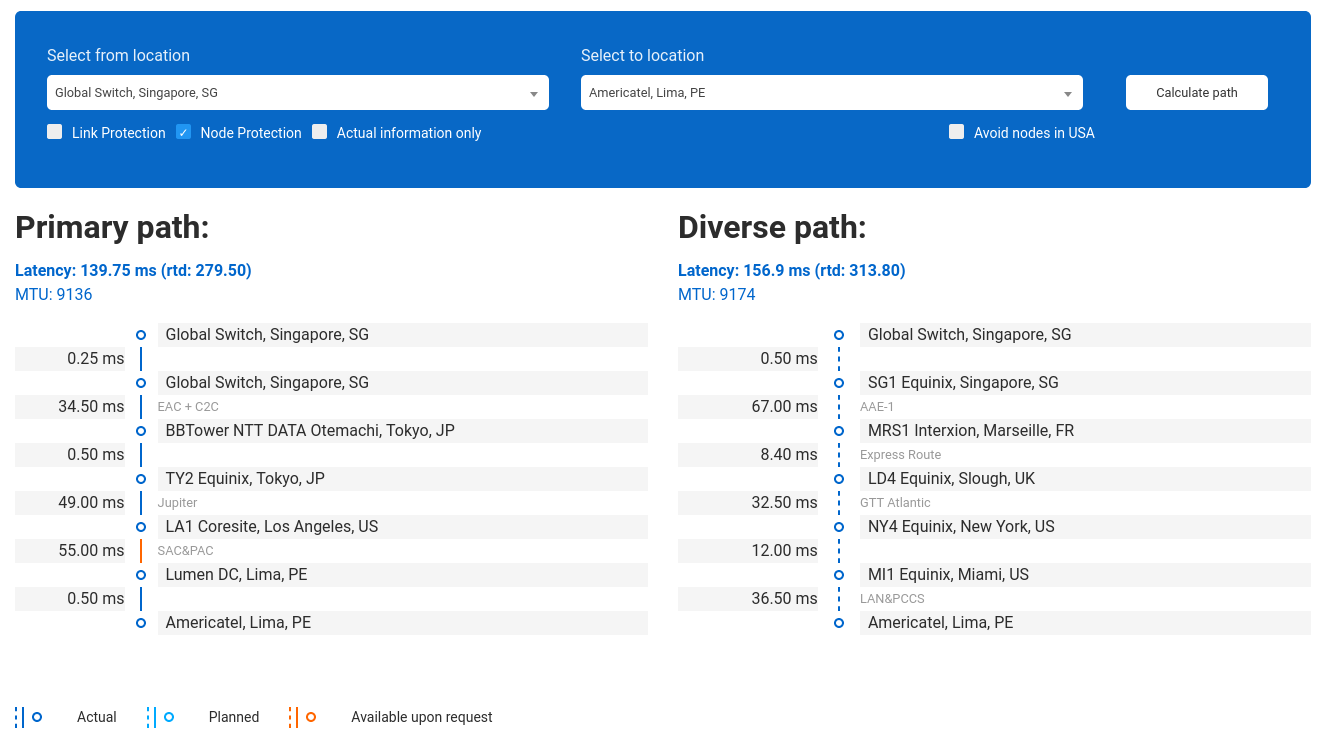
Node protection:
But if you also want to avoid the POP used in the Primary one, please choose “Node Protection”.
Actual Information Only:
Box to view just the on-net paths, not the “Available upon request” or «Planned» ones.
Avoid nodes in the USA
Click on “Avoid nodes in the USA” to see routes that do not have a stop in this region.
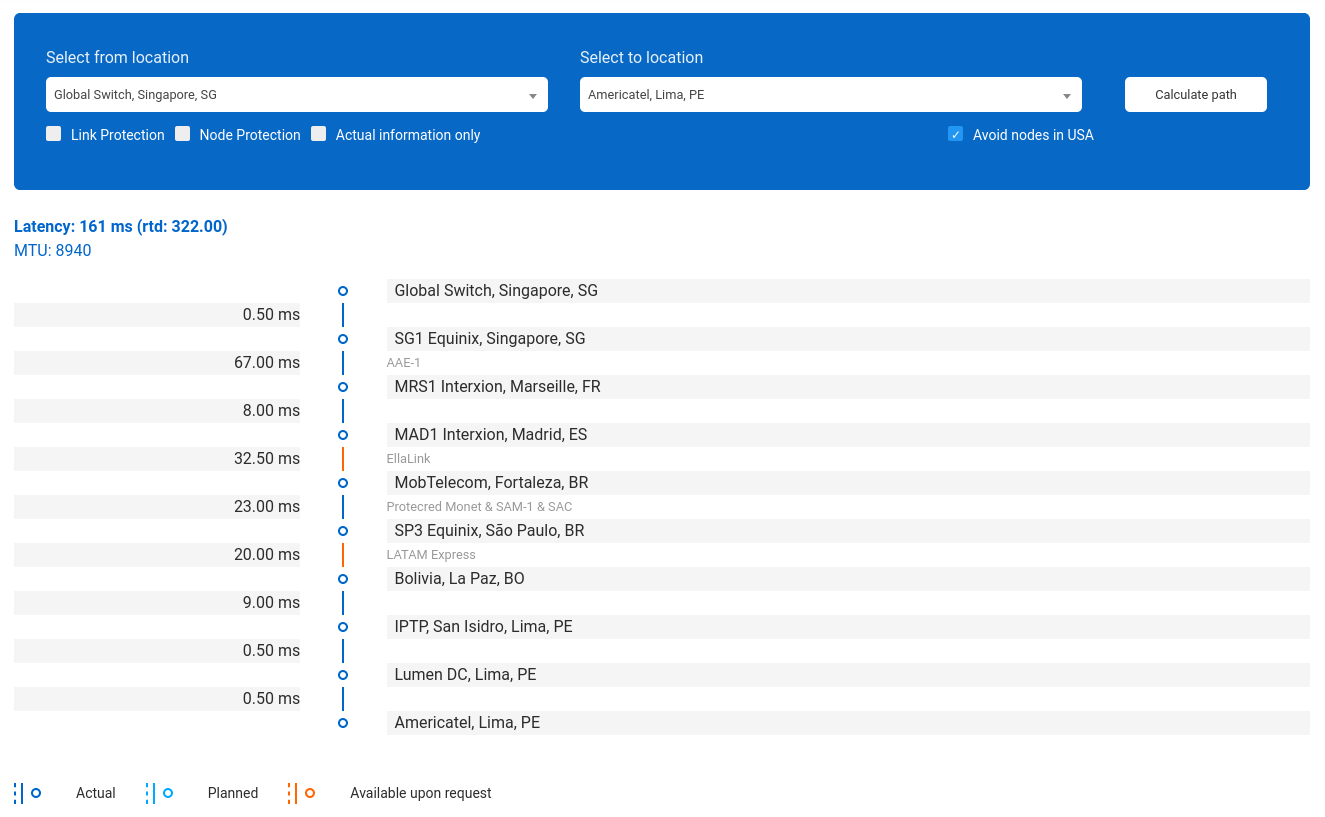
In this example, “LA1 Coresite, Los Angeles, US” is removed.
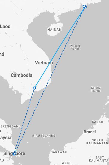
The Primary path is illustrated in the map as a solid line, while the Diverse path appears as a dashed line. Despite the form, the colour of those lines still has the same meaning as mentioned above:
Dark blue line: actual route,
Light blue line: a planned route for upcoming time,
Orange line: routes are available only when requested.
For example, you can see in this picture: the Primary path is a light blue solid line (Planned), while the Diverse path is a dark blue dash line (Actual).
As a combination with using this Best Path tool,
To have a better look at IPTP’s Network map, visit Network map.
To read more about our global backbone, network optimization, and low latency connectivities, please take a look at our Low Latency routes service.
To transparently connect HQ and branch offices worldwide to establish a strong backbone without decreasing performance or changing settings, do not forget our EoMPLS Pseudowire Service.